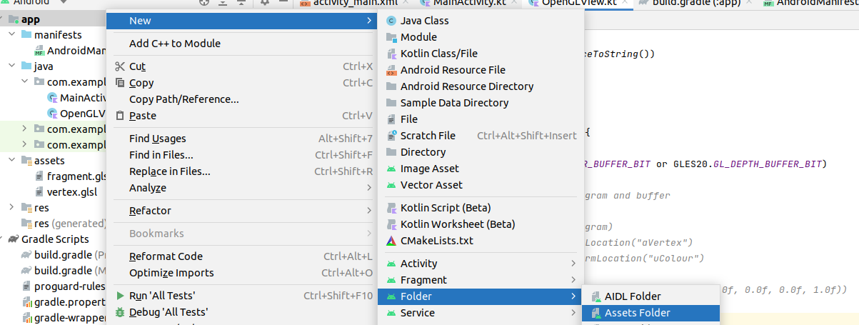
assets folder yourself. Right-click on the "app" folder and then select "New" and "Directory", as shown below:
Important! In this first week on OpenGL, we will not be dealing with the difference between world and eye coordinates in our code. Instead the camera will be placed at the origin, facing negative z, so world and eye coordinates will be equivalent. Furthermore, we will not yet be applying any sense of perspective, so all shapes we draw will have a z coordinate of 0.
An Android OpenGL application includes the following components:
You need to provide implementations of these three methods.
Here is an absolute basic example of an Android OpenGL application. It does not draw any graphics; it just shows you how you setup the OpenGL environment, and initialises a black screen ready for rendering 3D content. First we would have a main activity, as always:
package com.example.opengl

import androidx.appcompat.app.AppCompatActivity
import android.os.Bundle

class MyActivity: AppCompatActivity() {
    override fun onCreate(savedInstanceState: Bundle) {
        val glView = OpenGLView(this)
        setContentView(glView)
    }
}
We create an object of class OpenGLView which extends from GLSurfaceView (see below) and make this the main view of our activity. Now we move on to the OpenGLView object:
package com.example.opengl

import android.opengl.GLSurfaceView
import android.content.Context

class OpenGLView(ctx: Context)  :GLSurfaceView(ctx), GLSurfaceView.Renderer {
    init {
        setEGLContextClientVersion(2) // specify OpenGL ES 2.0
        setRenderer(this) // set the renderer for this GLSurfaceView
    }

    // We initialise the rendering here
    override fun onSurfaceCreated(unused: GL10, config: EGLConfig) {
        // Set the background colour (red=0, green=0, blue=0, alpha=1)
        GLES20.glClearColor(0.0f, 0.0f, 0.0f, 1.0f)

        // Enable depth testing - will cause nearer 3D objects to automatically
        // be drawn over further objects
        GLES20.glClearDepthf(1.0f)
        GLES20.glEnable(GLES20.GL_DEPTH_TEST)
    }

    // We draw our shapes here
    override fun onDrawFrame(unused: GL10) {
        GLES20.glClear(GLES20.GL_COLOR_BUFFER_BIT or GLES20.GL_DEPTH_BUFFER_BIT)
    }

    // Used if the screen is resized
    override fun onSurfaceChanged(unused: GL10, w: Int, h: Int) {
        GLES20.glViewport(0, 0, w, h)
    }
}
Note here:
init block, we specify that we are using OpenGL ES version 2.0 with
setEGLContextClientVersion(2) and then specify that the current object will act
as the renderer with setRenderer(this).In order to make using OpenGL easier, I have created an Android library, `OpenGLWrapper`, which makes writing basic OpenGL applications simpler. The raw OpenGL library requires you to make many method calls, some of which require many parameters to be passed which do not change 99% of the time. `OpenGLWrapper` makes the process of basic OpenGL development simpler.
To use:
https://github.com/nickw1/OpenGLWrapper
app/build/outputs/aar/app-debug.aar
GLSurfaceView as described above, as well as a MainActivity.libs folder inside app in your own project.implementation files('libs/app-debug.aar')freemap.openglwrapper package and must be imported from here.The code above obviously does not do anything. To get it to draw shapes, we
first of all need to define our vertex and fragment shaders. Where do we store our shaders? There is no standard way, but a common place to store them is within the assets folder of an Android project. You need to create two files, one for the vertex shader and one for the fragment shader, and save them in assets with extension .glsl.
You have to create the assets folder yourself. Right-click on the "app" folder and then select "New" and "Directory", as shown below:
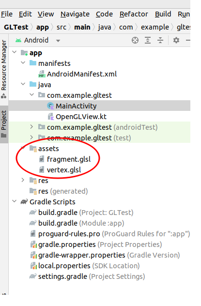
You will then end up with an assets folder. You should then right click on the assets folder and create two new files, vertex.glsl and fragment.glsl for your two shaders:
First the vertex shader:
attribute vec4 aVertex;
void main(void)
{
    gl_Position = aVertex;
}
Then the fragment shader:
precision mediump float;
uniform vec4 uColour;
void main(void)
{
    gl_FragColor = uColour;
}
You then need to compile the shaders into native GPU machine code. This is relatively easy with OpenGLWrapper. Add the following to the template code above:
GPUInterface. This class effectively acts as an interface to the GPU, and you use it to communicate with the shaders.
val gpu = GPUInterface("DefaultShaderInterface")
onSurfaceCreated(), compile and link the shaders, being careful to trap errors:
try {
    val success = gpu.loadShaders(context.assets, "vertex.glsl", "fragment.glsl")
    if (!success) {
        Log.e("OpenGLBasic", gpu.lastShaderError)
    }
} catch (e: IOException) {
    Log.e("OpenGLBasic", e.stackTraceToString())
}
assuming that vertex.glsl and fragment.glsl are the filenames of your vertex shader and fragment shader, respectively. Note that context.assets references your project's assets, within the assets folder; as we saw above, the shader source code is placed within the assets.IOException if the files do not exist. Note how we catch the IOException above, and display the error to the log.gpu.loadShaders() to return false, so if false is returned, we log the most recent shader error.What is actually going on inside loadShaders()?
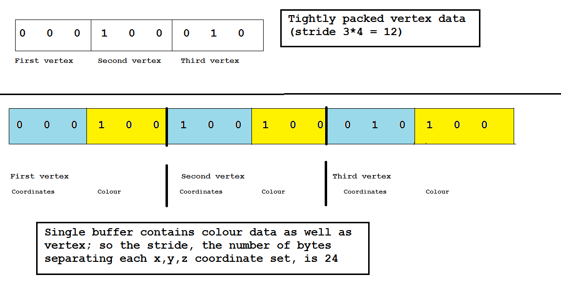
GPUInterface class contains within it a reference to this shader program. gpu.select() to specify that we want to use this shader program, not another one. It is possible for a single OpenGL application to have several shader programs which we can switch between; we would create several GPUInterface objects if we wanted to do this. In fact, when it comes to adding a camera feed to our application, we will do this.onSurfaceCreated(), as we only need to do it once. Compiling and linking them each time we render a frame would be extremely inefficient.Remember from the discussion above that the vertex data needs to be sent to the GPU in a buffer. Here is how to create a buffer:
FloatBuffer? in your OpenGLView.Renderer object and set it to null. It will be initialised later.onSurfaceCreated(), create a float array of the vertices you want to store in the buffer, and create the buffer using the OpenGLUtils.makeFloatBuffer() method. The example below creates a buffer with three vertices making up a triangle, with coordinates (0,0,0) , (1,0,0) and (0, 1, 0).
val vertices = floatArrayOf(
                0f, 0f, 0f,
                1f, 0f, 0f,
                0f, 1f, 0f
            )

fbuf = OpenGLUtils.makeFloatBuffer(vertices)
onSurfaceCreated(), as we only need to do it once. Doing it each time we render a frame would be very inefficient.Having setup our buffers we need to draw the shape(s) they contain in onDrawFrame().
To do this we need to send the buffered data to the GPU and
tell the GPU about the format of our data. How do we do that?
The next thing we need to do is to link our buffer data to a shader variable, so that the shader can process each vertex in the buffer in turn.
To be able to use a shader variable from Kotlin, we need to get
a "handle" on it to allow Kotlin to manipulate it, and then link this
"handle" to our vertex data. To obtain the "handle", we can use the method
getAttribLocation(), e.g.
val handle = gpu.getAttribLocation("aVertex")
The name of the shader variable needs to be passed to gpu.getAttribLocation().
Here is a code example, which
stores the handle in the variable ref_aVertex (note how we use
the shaderProgram variable which we created when we compiled and linked the shader).
// Create a reference to the attribute variable aVertex
val ref_aVertex = gpu.getAttribLocation("aVertex")
We can also get a handle on uniform variables. Remember from the discussion above that a uniform variable is a variable whose values do not vary from vertex to vertex. A good example of a uniform variable is a colour (assuming the shape is of a uniform colour). GLES20.glGetUniformLocation() works in exactly the same way as GLES20.glGetAttribLocation() e.g.
val ref_uColour = gpu.getUniformLocation("uColour")
Having obtained a reference to the uniform variable from outside our shader, we
then need to send data to it.
The method gpu.setUniform4FloatArray() can be used to send a 4-member array (hence the 4 in the method name) to the shader, containing the drawing colour.
The array's 4 members include red, green, blue and alpha - i.e. transparency - components.
Here is an example. Note how we pass in the reference to the shader variable and the array we want
to send.
val red = floatArrayOf(1.0f, 0.0f, 0.0f, 1.0f)
gpu.setUniform4FloatArray(ref_uColour, red)
Now onto the actual drawing itself. Our example buffer above contains six vertices, making up two triangles - so we are going to draw those triangles. Having placed the vertices in a buffer and obtained a handle on the shader variable which will contain each vertex, we can now actually draw the shape. Drawing a shape is performed by specifying a buffer or buffers to use (we could have one buffer for vertices and another for colours, for example) and then telling Android OpenGL ES 2.0 what format the buffer data is in and what shader variable should receive the buffered data. Here is how to do this.
specifyBufferedDataFormat():
gpu.specifyBufferedDataFormat(ref_aVertex, fbuf, 0)This is an interesting function as it takes several arguments:
gpu.drawBufferedTriangles(0, 3)The first argument 0 is the index of the first vertex, and the second argument 3 is the number of vertices in total.
The previous example could be extended very easily to draw two triangles.
The only differences are that we would fill the buffer with 6 points rather
than 3, and change the gpu.drawBufferedTriangles() call to reflect this:
gpu.drawBufferedTriangles(0, 6)The method will know to treat each set of three vertices as a separate triangle.
Another example:
gpu.drawBufferedTriangles(3, 3)If the buffer had at least 6 vertices (i.e. at least 2 triangles), this would draw the second triangle only because the start vertex is 3 (the first vertex of the second triangle), and the number of vertices to draw is 3.
Look at this diagram:
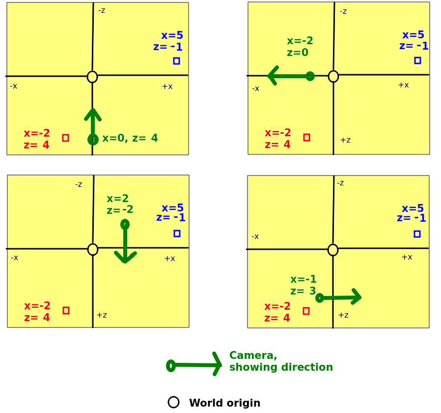
For each of the four diagrams, state the eye coordinates of the red and blue boxes. The world coordinates of the camera and of the red and blue boxes are shown in each case.
We are going to develop a simple OpenGL application to draw first one, then two red triangles, and finally two triangles in different colours.
gpu : a GPUInterface, allowing you to compile and communicate with shaders running on the GPU, as described above.vertexBuffer : a nullable FloatBuffer. This will contain the vertices when loaded.onSurfaceCreated, add the methods provided above to load the shaders, and to initialise a vertex buffer using a float array of coordinates. Use the coordinates given above initially.onDrawFrame(), add the code (shown above) to obtain references to the shader variables (current vertex and colour), send a colour (red) over to the fragment shader, specify the buffered data format, and actually draw the triangle in the buffer. x=0, y=0, z=0 x=-1, y=0, z=0 x=0, y=-1, z=0