OpenGL is the standard API for cross-platform 3D graphics. With OpenGL you can create hardware-accelerated 3D graphics on a range of operating systems, including Windows, Linux, Mac OS X and Android. OpenGL takes advantage of a machine's Graphics Processing Unit (GPU) for fast rendering. In OpenGL, 3D shapes are made up of of individual triangles, each of which has three vertices (points making up the triangle).
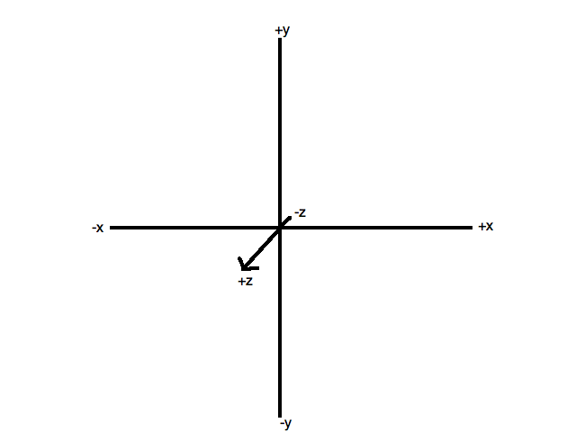
Since OpenGL is a 3D API, it uses three coordinates: x, y and z. It's important to realise that x increases to the right, and y increases upwards, This is different to the situation in 2D computer graphics, where y increases downwards - but is the same as in standard maths.
Because this is 3D graphics, we have a third axis, the z axis. You can think of this as pointing out at you from the screen, so that positive z coordinates are "in front of the screen" and negative z coordinates are "behind the screen". This is shown in the diagram below.
OpenGL ES is a version of OpenGL optimised for devices with limited resources, such as mobile devices (although these days many mobile devices have capabilities comparable with traditional desktop machines!) OpenGL ES programming is slightly different to standard OpenGL: it is somewhat more complex but more efficient. There are various versions of OpenGL ES: we will use OpenGL ES 2.0 as it provides what we need.
The API is significantly different to standard OpenGL. Drawing shapes takes on a different approach: rather than drawing each triangle individually, all vertices making up a complex shape are sent direct to the graphics card at once, in a buffer, for fast, efficient drawing.
When working with OpenGL, we have two coordinate systems. An OpenGL application typically comprises a virtual world which we can wander around, as a player in a game or a user of a VR or AR app. World coordinates define the position of objects within this virtual world. We also have the eye coordinate system. This describes the coordinates of objects with respect to the user's current view of the world, which may not be the same. We expand upon the difference below.
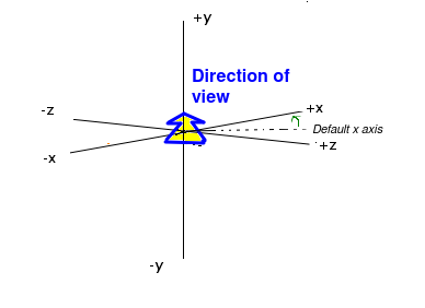
Typically, the coordinates of 3D objects in an OpenGL application will be specified in our code, or more commonly, in an external data source such as a file or the web. The coordinates of these objects are with respect to our virtual world, and can be thought of as the "true" coordinates of the objects within our 3D world - thus they are world coordinates. They define the absolute position of each object in our virtual world - in that respect they are conceptually similar to latitude and longitude. However, our view of the coordinates might be different. Imagine the origin of the 3D world is the central room in a 3D game. We might not be at that position in the world, we might be in a completely different room, and furthermore, we might not be looking down the negative z-axis as in the default view. We might be looking in a direction aligned at 45 degrees to both the x and z axes, as shown in the diagram below. Additionally, we might be on a slope, in which case, the up direction does not correspond to the y axis.
The current on-screen 3D coordinates of a given object, with respect to the user's current view, are the eye coordinates of that object. The eye coordinate (0,0,0) is always the user's position within the world. And in eye coordinates, we are always facing negative z, with x increasing to the right and y increasing upwards, even if we are not facing negative z in world coordinates.
When rendering 3D shapes, we use eye coordinates, because we want to render them with respect to the current view. Thus we have a problem, because the shapes will typically be stored in a file or on the web as world coordinates. So we have to define a transformation to convert the world coordinates to eye coordinates. This transformation has two components:
In many 3D applications, we want to allow the user to navigate through a 3D world, e.g. (as we have seen) a game or a VR or AR app. In these cases, we define the objects making up the world (which might include 3D buildings, terrain, points of interest, etc) in our code as world coordinates. We then define a camera, which represents the user's position in the world and the direction in which they are facing. Such a camera would have a set of world coordinates defining its position within the world, as well as a rotation. Such a camera, representing the user's position, is known as a first-person camera; other types of camera also exist which present a view of the world from the perspective of something other than the user (e.g. from the perspective of a certain room in a game, or a non-player character).
The world coordinates of the camera would vary, as the camera moves round the world. However, because a first-person camera represents the user's position, its eye coordinates will always be x=0, y=0, z=0.
As seen above, the camera has a position and rotation. In more detail, it has:
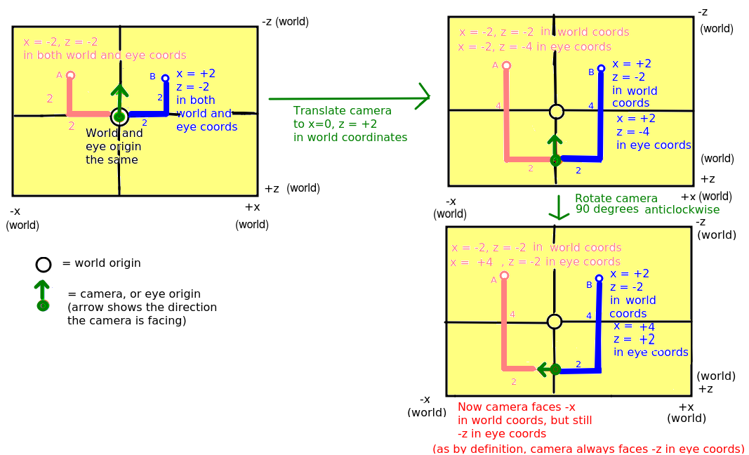
We are going to examine how the eye coordinates of points A and B change as we move the camera.
It's important to not get confused by the terminology here. The first-person OpenGL camera is not the same as the actual hardware camera used to take pictures on the device. When we move onto AR, we will use the term "hardware camera" to distinguish the physical camera from the OpenGL camera.
See here.
Many of you will have come across matrices in the past, at school or college. Matrices are two-dimensional arrays of numbers which are most commonly used to represent geometric transformations which can be applied to shapes (both 2D and 3D), such as rotation, translation, magnification, stretch and shear. There are also other, more specialised, applications of matrices in science and maths - but these are out of the scope of this module. We will not go into the maths of matrices in great detail, but you need to be aware that a matrix represents a geometric transformation of some kind, such as translation or rotation. You also need to be aware of various matrices which exist within OpenGL which are involved in the rendering process. We will expand upon matrices a little next week.
OpenGL defines a matrix which specifies the transformation between the world coordinates and the eye coordinates. This is called the view matrix. Every time you do a translation or rotation in code, the view matrix is multiplied by the matrix which defines that rotation/translation. Then finally the coordinates specified in code (the world coordinates) are multiplied by the view matrix to give the coordinates with respect to the user's current view.
The other type of matrix which is used in OpenGL is the projection matrix. This transforms the coordinates of shapes to add a sense of perspective, in other words it makes nearby shapes appear larger and further-away shapes appear smaller. So, shapes with eye z coordinates close to 0 (e.g. -1, -2) will appear relatively large, whereas shapes with negative z coordinates further from 0 (-10, -20, etc) will appear smaller. Without the projection matrix, no perspective is applied and shapes would appear the same size irrespective of their eye z coordinate. In fact, the exercises this week will not involve the projection matrix, and therefore, even though you will be doing some OpenGL programming the shapes you draw will appear flat, without a sense of perspective.
An Android OpenGL ES 2.0 application consists of:
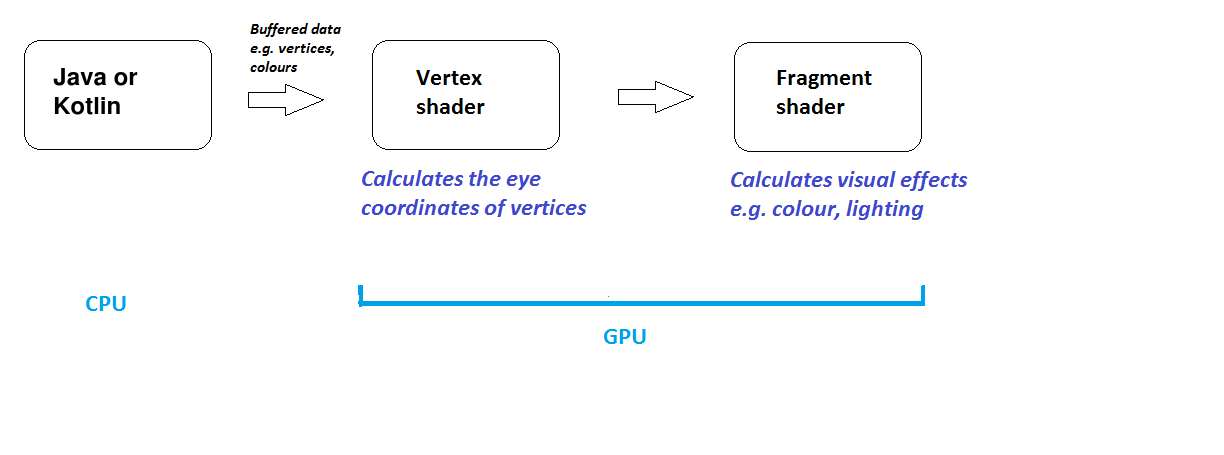
Android OpenGL ES 2.0 applications thus take place partly on the CPU and partly in the GPU (via shaders). A Android OpenGL ES 2.0 application generally works in this way:
This discussion applies to OpenGL ES in general; not just Android OpenGL ES 2.0.
Android OpenGL ES 2.0 (and all OpenGL ES 2.0 implementations) require the use of shaders. Shaders are small programs, written in a C-like language, GLSL (GL Shader Language), which run on the graphics card (GPU) and specify how vertices, and thus shapes, appear on the screen (position, colour, lighting, textures etc). A shader-based OpenGL application will consist of a CPU based program plus a series of shaders running on the GPU. The CPU program passes information to the shaders through a process known as the rendering pipeline.
There are two types of shader:
There are three classes:
attribute vec4 aVertexPosition;
void main(void)
{
    gl_Position = aVertexPosition;
}
void main (void)
{
    gl_FragColor = vec4(1.0, 0.0, 0.0, 1.0);
}
In this example we read in the colour from the uniform variable uColour.
precision mediump float;
uniform vec4 uColour;

void main(void)
{
    gl_FragColor = uColour;
}
Note the three lines at the top, which specify that we are using high-precision floats.
This is needed if you pass across variable colours to the fragment shader.