Mobile Development and 3D Graphics - Part 8
OpenGL part 2
Today we will continue to look at OpenGL by examining matrix transformations in more detail, and look at the view and projection matrices and how we can send them to the shader.
More on matrices
As we saw last week, a matrix is a "grid" of numbers representing a particular transformation in 2D or 3D space. Matrices can be applied to coordinates (defining shapes, for example) to change (transform) them in some way. These transformations include translations (moving a shape around the world), scaling (making a shape bigger or smaller in one or more axes), or rotations (rotating an object around the x, y or z axis). In the case of OpenGL, we are mostly interested in translations and rotations.
Here is an example of a 3x3 matrix:
[1 0 0]
[0 1 0]
[0 0 1]
When applying matrices to points, we typically represent the points in vector form, so a point (x,y,z) would become:
[x]
[y]
[z]
Technically a vector represents a movement in space from one point to another, and contains the change in the x, y and z dimensions. However for the purposes of this discussion, we are just using a vector to represent a point in a form which allows it to be multiplied by a matrix.
Multiplying vectors and matrices
There is a predefined formula for multiplying a vector by a matrix to produce an output vector, which is:
[a b c]      [x]         [ax + by + cz]
[d e f]  *   [y]   =     [dx + ey + fz]
[g h i]      [z]         [gx + hy + iz]
Note how we multiply the rows by the columns. So the first component (x component) of the output vector will be the result of multiplying each term in the first row of the matrix with the corresponding term in the vector, and then summing them together. The second component (y component) of the output vector will be the result of multiplying each term in the second row of the matrix with the corresponding term in the vector, and summing them together. And the third component (z component) of the output vector will be the result of multiplying each term in the third row of the matrix with the corresponding term of the vector, and summing them together.
The identity matrix
A matrix which has no effect on the input vector is called an identity matrix. An identity matrix has 1 values along the main diagonal from top left to bottom right, and zeros elsewhere. We can show that the identity matrix has no effect from the above equation, as a=1, e=1, i=1 and all other values in the matrix are 0:
[1 0 0]      [x]         [1x + 0y + 0z]    [x]
[0 1 0]  *   [y]   =     [0x + 1y + 0z] =  [y]
[0 0 1]      [z]         [0x + 0y + 1z]    [z]
Questions
What effect will these matrices have on a point (x,y,z) ?
[2 0 0]
[0 2 0]
[0 0 2]
[3 0 0]
[0 1 0]
[0 0 1]
Transforming shapes using matrices
To perform a transformation on a shape using a matrix, you have to multiply each point in the shape by the matrix, using the multiplication technique shown above.
Multiplying matrices
The same principle involves multiplying two matrices together, for example two 3x3 matrices. This produces an output matrix. This allows us to use a single matrix to apply two transformations in one go. If two matrices representing different transformations are multiplied, the resulting matrix performs both operations in one step.
Here is an example of 3x3 matrix multiplication (note lower-case and upper-case letters represent different values). It's an extension of the same principle as multiplying a matrix and a vector.
[a b c] [A B C]   [aA+bD+cG aB+bE+cH aC+bF+cI]
[d e f] [D E F] = [dA+eD+fG dB+eE+fH dC+eF+fI]
[g h i] [G H I]   [gA+hD+iG gB+hE+iH gC+hF+iI]
The value at position (row, col) of the output matrix consists of each value of row row from the first matrix multiplied by the corresponding value of column col from the second matrix and summed together. So, for example:
- The value at position
(row=0,col=0) in the output matrix consists of each value of row 0 from the first matrix multiplied by the corresponding value of column 0 from the second matrix and summed together.
- The value at position
(row=0,col=1) in the output matrix consists of each value of row 0 from the first matrix multiplied by the corresponding value of column 1 from the second matrix and summed together.
- The value at position
(row=1,col=0) in the output matrix consists of each value of row 1 from the first matrix multiplied by the corresponding value of column 0 from the second matrix and summed together.
- The value at position
(row=1,col=2) in the output matrix consists of each value of row 1 from the first matrix multiplied by the corresponding value of column 2 from the second matrix and summed together.
Hopefully you can work out from the above that in matrix multiplication, the order of multiplication matters. So A*B is not the same as B*A. The result of multiplying the two matrices above in the reverse order would be different:
[A B C] [a b c]   [Aa+Bd+Cg Ab+Be+Ch Ac+Bf+Ci]
[D E F] [d e f] = [Da+Ed+Fg Db+Ee+Fh Dc+Ef+Fi]
[G H I] [g h i]   [Ga+Hd+Ig Gb+He+Ih Gc+Hf+Ii]
Matrix example
See here. This is 2D only, but allows you to experiment with applying matrices to a 2D shape on a graph to see what effect it has. Note that the example stores a current matrix, which is the product of all previous matrices, i.e. it is multiplied by each new matrix entered. So a transformation will be combined with the previous transformation, unless you click the "Reset Matrix" button. This resets the current matrix to the identity matrix.
Specific examples of matrix transformations
These are 2D examples.
Anticlockwise rotation by 90 degrees
[0  -1]
[1   0]
Clockwise rotation by 90 degrees
[ 0  1]
[-1  0]
Reflection in the line x=y
This swaps the x and y coordinates.
[0  1]
[1  0]
Rotations about the x, y and z axes
In OpenGL we are particularly interested in rotation and translation so we will look at these now.
In 2D, i.e. a graph with x and y axes only, the rotation about a given angle A (anticlockwise) is given by:
[cos A    -sin A]
[sin A     cos A]
We can apply this matrix to each point in a shape, to rotate that shape by the given angle. In 3D it's an extension of the same idea:
Rotation about the x-axis
[1     0      0    ]
[0     cos A -sin A]
[0     sin A  cos A]
About the y-axis
[cos A  0      sin A]
[0      1      0    ]
[-sin A 0      cos A]
About the z-axis
[cos A  -sin A  0    ]
[sin A   cos A  0    ]
[0      0       1    ]
4x4 Matrices in OpenGL
4x4 Matrices
In 3D graphics it's commonplace to use 4x4 matrices rather than
3x3. The reason why this is, is that they allow you to combine the translation
and rotation into a single matrix.
For example remember that
the standard matrix for rotating about the y axis anticlockwise by a given
angle A is:
[cos A    0     sin A]
[0        1         0]
[-sin A   0     cos A]
Translations, by contrast, are represented by vectors. We saw above that a vector represents a movement in space. So we could represent a translation by dx in the x direction, dy in the y direction, and dz in the z direction as:
[dx]
[dy]
[dz]
Can we just multiply the two together? No, because a matrix multiplied by a vector would give another vector, whereas what we want is a matrix representing the rotation and translation in one step. What we can do, however, is represent the translation vector in matrix form by combining it with an identity matrix:
[1 0 0 dx]
[0 1 0 dy]
[0 0 1 dz]
However, this will not quite work. If we wanted to use this to transform a vector such as:
[3]
[4]
[5]
we would be unable to, because matrix multiplication involves multiplying the rows of the first matrix with the columns of the second. For this to work, the number of columns in the first matrix must be equal to the number of rows in the second, and here, it is not (matrix has four columns, vector has three rows).
To deal with this, we pad out the matrix with an additional line of zeros and ones which will have no impact on the result:
[1 0 0 dx]
[0 1 0 dy]
[0 0 1 dz]
[0 0 0  1]
and use a four-member vector for our point (x,y,z), with a one as the fourth member (this allows the translation component to be applied, which it would not if it was zero):
[3]
[4]
[5]
[1]
A combined 4x4 rotation-translation matrix
We can similarly pad out our rotation matrix with zeros and ones which will have no impact on the result, in order to make it a 4x4 matrix and thus make it able to be multiplied with the translation matrix:
[cos A   0      sin A   0 ]
[0       1      0       0 ]
[-sin A  0      cos A   0 ]
[0       0      0       1 ]
Then, if we multiply the two together (rotation matrix * translation matrix, NOT translation * rotation, as the order of matrix multiplication matters - we will look at this in more detail next week), we get a combined matrix which is:
[cos A   0      sin A   dz]
[0       1      0       dy]
[-sin A  0      cos A  -dx]
[0       0      0       1 ]
This matrix will perform a rotation (anticlockwise) by the angle A, and
translate the coordinates by dx in the x direction, dy in the y
direction and dz in the z direction. If dx, dy and dz are 0, then only a
rotation will be performed. If A is 0, then only the translation will be
performed.
Relation to the view matrix
We saw last week that the view matrix represents the transformation from world to eye coordinates, and consists of both a translation and a rotation component. Therefore, the view matrix is actually a 4x4 matrix, of the form discussed above.
Communicating matrices to the vertex shader
We saw last week that the vertex shader is responsible for transforming world coordinates to eye coordinates using the view matrix. How do we manage this in code? We need to define a 16-member float array (4 rows * 4 columns) in our Kotlin, and then send it to the shader using a similar technique to last week. The view matrix on the shader is a uniform variable, because it stays the same for all vertices for the current rendering frame of our 3D scene. However, each time the scene changes (e.g. when it is rotated, or when the user changes position) we will need to update the matrix.
How do we do this? We typically use a variable within Kotlin to store the view matrix and update this matrix within Kotlin in response to user interaction (such as the user moving through the 3D world or rotating the field of view). Then, we send it to the vertex shader so that next time the scene is rendered, the new matrix will be used. Here is the detail on how to do this.
Add a float array to your Renderer
Your Renderer class needs to contain an object containing the view matrix, e.g.:
val viewMatrix = GLMatrix()
GLMatrix is part of the GLWrapper library.
A vertex shader using the view matrix
We will look at a vertex shader which actually transforms the vertices by the view matrix.
attribute vec4 aVertex;
uniform mat4 uView;

void main(void)
{
    gl_Position = uView*aVertex;
}
Note how in this vertex shader we calculate the vertex position
on-screen (eye coordinates) by multiplying the input vertex position
(world coordinates; from the data model) by the view
matrix. We need to convert the input vertex position from
a 3-element to a 4-element vector due to the view matrix being a 4x4 matrix.
With matrix multiplication (we are treating the vector as a 4x1 matrix), the number of rows of the first matrix must be equal to the number of columns of
the second.
The projection matrix
We have come across the view matrix already. However, we also need to use the projection matrix to apply perspective effects (making nearby objects look larger than further-away objects and giving a sense of depth). To do this, we must define the viewing frustum.
The viewing frustum
To calculate the projection matrix, you need to define the current visible area of the world with four parameters:
- The field of view: the angle describing the current visible area in degrees (180 degrees would mean you can see the half of the world in front of you, but normally the field of view is less than that
- The aspect ratio, which is the width of the GLSurfaceView divided by the height.
- The near clipping plane. This plane defines the closest distance to the camera that can be seen, and is typically very close to the camera.
- The far clipping plane. This plane defines the furthest distance from the camera that can be seen.
These four parameters together define a shape, resembling a pyramid with the top sawn off, called the viewing frustum. The viewing frustum defines the visible area of the world, and is shown below.
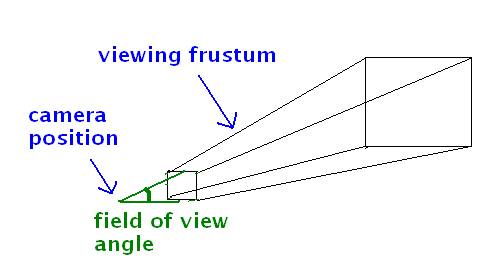
When we define the viewing frustum with these four parameters, we also calculate the projection matrix.
Using the projection matrix
To use the projection matrix, you need to:
- Create a
GLMatrix in your Renderer to hold it, e.g:
val projectionMatrix = GLMatrix()
- Include it in the vertex shader, so that each vertex is transformed by both the view and projection matrices:
attribute vec4 aVertex;
uniform mat4 uView, uProjection;

void main (void) {
    gl_Position = uProjection * uView * aVertex;
}
- Add code to your
onSurfaceChanged() method to calculate the projection matrix each time the dimensions of the GLSurfaceView change.
override fun onSurfaceChanged(unused: GL10, w: Int, h: Int) {
    GLES20.glViewport(0, 0, w, h)
    val hfov = 60.0f
    val aspect : Float = w.toFloat()/h
    projectionMatrix.setProjectionMatrix(hfov, aspect, 0.001f, 100f)

}
How is this working?
- We set the horizontal field of view. This is the field of view, in
degrees, that we can currently see in the scene (60 degrees here)
- We call
GLES20.glViewport() to ensure the OpenGL viewport matches the screen size.
- We then calculate the aspect ratio (width divided by height)
- We then call
OpenGLUtils.fillProjectionMatrixc() to set the perspective.
The arguments are:
- the horizontal field of view;
- the aspect ratio;
- the near clip plane (0.001)
- the far clip plane (100).
- Send the projection matrix to the corresponding uniform
variable in the shader, in exactly the same way we did with the view
matrix, i.e:
ref_uProjMatrix = gpu.glGetUniformLocation("uProjection")
gpu.sendMatrix(ref_uProjMatrix, projectionMatrix)
Exercise - View and Projection Matrices
Add this layout to your app (you will need to add appropriate string resources for the buttons):
<androidx.constraintlayout.widget.ConstraintLayout xmlns:android="http://schemas.android.com/apk/res/android"
    xmlns:app="http://schemas.android.com/apk/res-auto"
    xmlns:tools="http://schemas.android.com/tools"
    android:layout_width="match_parent"
    android:layout_height="match_parent"
    tools:context=".MainActivity">

    <Button
        android:layout_width="0px"
        android:layout_height="wrap_content"
        android:id="@+id/minusX"
        android:text="@string/minusX"
        app:layout_constraintTop_toTopOf="parent"
        app:layout_constraintLeft_toLeftOf="parent"
        app:layout_constraintRight_toLeftOf="@id/plusX" />
    <Button
        android:layout_width="0px"
        android:layout_height="wrap_content"
        android:id="@+id/plusX"
        android:text="@string/plusX"
        app:layout_constraintTop_toTopOf="parent"
        app:layout_constraintLeft_toRightOf="@id/minusX"
        app:layout_constraintRight_toLeftOf="@id/minusY" />
    <Button
        android:layout_width="0px"
        android:layout_height="wrap_content"
        android:id="@+id/minusY"
        android:text="@string/minusY"
        app:layout_constraintTop_toTopOf="parent"
        app:layout_constraintLeft_toRightOf="@id/plusX"
        app:layout_constraintRight_toLeftOf="@id/plusY" />
    <Button
        android:layout_width="0px"
        android:layout_height="wrap_content"
        android:id="@+id/plusY"
        android:text="@string/plusY"
        app:layout_constraintTop_toTopOf="parent"
        app:layout_constraintLeft_toRightOf="@id/minusY"
        app:layout_constraintRight_toLeftOf="@id/minusZ" />

    <Button
        android:layout_width="0px"
        android:layout_height="wrap_content"
        android:id="@+id/minusZ"
        android:text="@string/minusZ"
        app:layout_constraintTop_toTopOf="parent"
        app:layout_constraintLeft_toRightOf="@id/plusY"
        app:layout_constraintRight_toLeftOf="@id/plusZ" />

    <Button
        android:layout_width="0px"
        android:layout_height="wrap_content"
        android:id="@+id/plusZ"
        android:text="@string/plusZ"
        app:layout_constraintTop_toTopOf="parent"
        app:layout_constraintLeft_toRightOf="@id/minusZ"
        app:layout_constraintRight_toRightOf="parent"  />

    <!-- you may need to change the package -->
    <com.example.opengl1.OpenGLView
        android:layout_width="0px"
        android:layout_height="0px"
        android:id="@+id/glview"
        app:layout_constraintBottom_toBottomOf="parent"
        app:layout_constraintEnd_toEndOf="parent"
        app:layout_constraintStart_toStartOf="parent"
        app:layout_constraintTop_toBottomOf="@id/minusX" />

</androidx.constraintlayout.widget.ConstraintLayout>
and change your main activity to use this layout. Also change your OpenGLView to have different parameters:
class OpenGLView(ctx: Context, aset: AttributeSet) :GLSurfaceView(ctx, aset) {
which is necessary to load the OpenGLView from XML.
This is an enhanced GUI containing
buttons allowing you to move the camera around. This will be used for a
later exercise.
- Add two
GLMatrix objects to the Renderer (as attributes, i.e. directly within the class, not in methods) to represent the view and projection matrices:
val viewMatrix = GLMatrix()
val projectionMatrix = GLMatrix()
In the onDrawFrame(), initialise the view matrix to an identity matrix, so that initially it has no effect, e.g:
viewMatrix.setAsIdentityMatrix()
- Write an
onSurfaceChanged() method like the example above, to setup the projection matrix.
- Alter your vertex shader so that the vertices are transformed by the perspective and view matrices, as shown in the example above.
- In your
onViewCreated(), create a float array containing vertices for two triangles:
- Triangle 1: (0,0,-3), (1,0,-3), (0.5,1,-3)
- Triangle 2: (-0.5, 0, -6), (0.5, 0, -6), (0, 1, -6)
and create a vertex buffer containing all 6 vertices (i.e. 18 float values in total). Draw these triangles, in two different colours, in your onDrawFrame().
- Try it out. In your onDrawFrame() you should send the view and projection matrices to the shader and then draw your two triangles.
What effect do you get and why?
- Now, in
onDrawFrame(), and before you draw the shapes, try sending an altered view matrix to the shader. Initialise your view matrix to the identity matrix first (to ensure you blank out the previous one) and then use the API call
GLMatrix.translate() to translate the view matrix -1 in the z direction relative to its previous state:
viewMatrix.translate(0, 0, -1)
The arguments: 0=translation in x direction, 0=translation in y direction; -1=translation in z direction.
The view matrix was initially the identity matrix:
[1 0 0 0]
[0 1 0 0]
[0 0 1 0]
[0 0 0 1]
The effect of translate() will be to convert it to:
[1 0 0  0]
[0 1 0  0]
[0 0 1 -1]
[0 0 0  1]
- What effect do you get, and why? Try using a range of different
z translations, between -2 and +2, see what effect it has, and try to explain your observations. We will go over this in class.
Discussion from Question 7 of above exercise
Now we have completed this week, I have added a discussion on this. You will note that setting the z translation to -1 makes the triangles appear smaller. Why is this? The diagram below helps explain it:
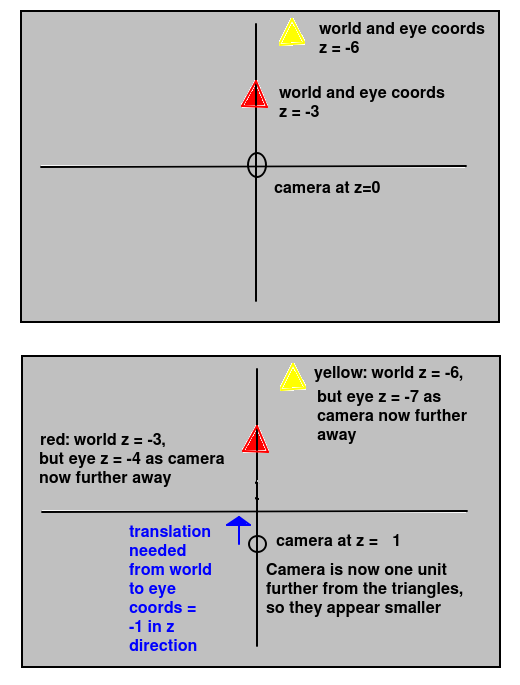
The -1 does not define the z coordinate of the camera. It defines the translation needed to convert world to eye coordinates. If this translation is -1, it means that the z coordinate of the camera must be +1. This is because, by definition, the camera is at the origin in eye coordinates. So the translation required to translate the camera from a world z coordinate of cz to zero must always be -cz. Or, looking at it the other way round, the world coordinate of the camera for a given world to eye translation of dz will be -dz. So here, if the translation dz is -1, the z coordinate of the camera must be +1. (The same principles also apply in the x and y directions).
You can also see from the diagram above that, when we move the camera to a z of +1, the distance to the two triangles increases by one unit (as they both have negative z coordinates) so the eye z coordinates of each will become one unit more negative (-3 to -4 and -6 to -7 for the red and yellow triangle respectively).
3D Worlds in OpenGL
A common application of OpenGL is a 3D game or virtual reality application where the player can move around. These applications have the concept of a camera, as we saw last week.
For example, a player in a game might be standing at the
position x=100, y=0, z=100 and facing along the x axis. How can we develop this sort of application in
OpenGL?
Express your objects in world coordinates
In this sort of application, all the objects in the world - as well as the camera - need to be stored in world coordinates. We then define a view matrix to transform the world coordinates to eye coordinates based on the position of the camera. We will need a Camera object. part of the OpenGLWrapper library, to represent the current camera position in x, y and z coordinatesand rotation in degrees. The camera can be created as follows:
val camera = Camera(x, y, z)
where x, y and z represent the initial position.
Try answering this question. If the camera position is at x=0, y=0, z=100 in world coordinates, and facing towards negative z, what translation do we need to do (expressed as a translation vector) to transform our world coordinates into eye coordinates for that position? (Think about your observations in the final question of Exercise 1).
Exercise 2
Enhance the app, so that it allows the user to move the camera one unit in the x, y and z directions, either positive or negative. Use the 6 buttons on your UI (provided by the code in the repository) to do this. You will need to:
- store the position of the camera as a
Camera object, as shown above.
- ensure that, each time
onDrawFrame() is called, the view matrix is re-initialised to an identity matrix. This is to ensure that, when the matrix is translated with GLMatrix.translate(), it is relative to the identity matrix and not relative to its previous value.
- write a set of methods in your renderer class to move the camera in the appropriate direction.
Each of these will need to update the
cameraPos float array accordingly
- call these methods from the appropriate button (do this inside the main activity).
- In your
onDrawFrame(), after initialising the view matrix as an identity matrix, use the camera position to set the view matrix appropriately using GLMatrix.translate(). The Camera has a position attribute with x,y and z properties. (How would you do this?)