UML: Unified Modelling Language
Object-oriented analysis and design makes use of UML. UML is an extensive set of diagrammatic tools to enable developers to
analyse a problem and design an object-oriented solution to the problem
before coding it. These diagrammatic tools include (but are not restricted to):
- Use-case diagrams
- Class diagrams
- Sequence diagrams
UML is not an analysis and design process; rather it is a set of
tools which can aid us in that process. It can be used in various different analysis and design techniques, such as ICONIX, discussed in a later week.
The problem statement
Analysis and design starts with a problem statement. This is a written description of what is required of the application, and will typically be produced by gathering requirements from the target users. Here is an example:
There is a requirement for a software application to allow a university
to manage its undergraduate and masters students and modules. Each student and
module is identified by a unique ID. University admins need to be able to look
up students and modules by ID, look up students by name, and enrol students on
modules. The system should record all modules a student is enrolled on.

Students are enrolled on a total of 6 modules.

It may be necessary to remove a student from the university or update the
student's contact details.
The domain model
The domain model is an initial diagram showing possible classes in the system, and their interaction. We derive it by:
- analysing the problem statement, and looking for
nouns and their interactions - these are our first guess at
classes in the system
- Having derived a list of possible objects, we then connect them
together to illustrate the relationship between them
For example, for the student records application, specified in the problem statement above, we could identify likely nouns as below:
There is a requirement for a software application to allow a
university to manage its undergraduate and masters students
and its modules. Each student and module is identified by a
unique ID. University admins need to be able to look up
students and modules by ID, look up students by name, and enrol
students on modules. The system should record all modules a student is enrolled
on.

Students are enrolled on a total of 6 modules.

It may be necessary to remove a student from the university or update the
student's contact details.
These likely nouns appear:
- university;
- student;
- module.
We also possibly have:
but these are just simple items of data which could be represented as numbers and strings and therefore do not need their own classes. Furthermore we also have:
- university administrator,
but this is a bit different. The administrator will be a
user of the software (an
actor - see discussion on use cases below), not an entity that the software needs to manage. We consider users later, when doing use cases. So from this analysis we could derive a domain model as below:
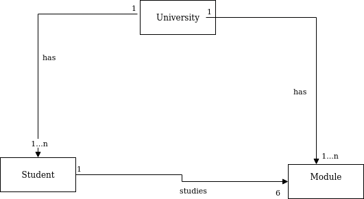
This shows the three possible classes in the system, and the relationship
between them as annotations.
Class diagrams
Class diagrams show the classes in the system,
their inter-relationships, and the attributes and methods of each class. The class diagram is an extension of the domain model, with attributes and methods added.
How to derive the class diagram
- Classes and their interrelationships come from the domain model
- When first analysing the problem statement, you can add a first guess at likely attributes and methods to the domain model to produce an initial class diagram
- The class diagram will be updated later, once we have gone through the full analysis and design process (robustness diagrams, sequence diagrams) as the full analysis and design will reveal additional methods and attributes
Class diagram syntax
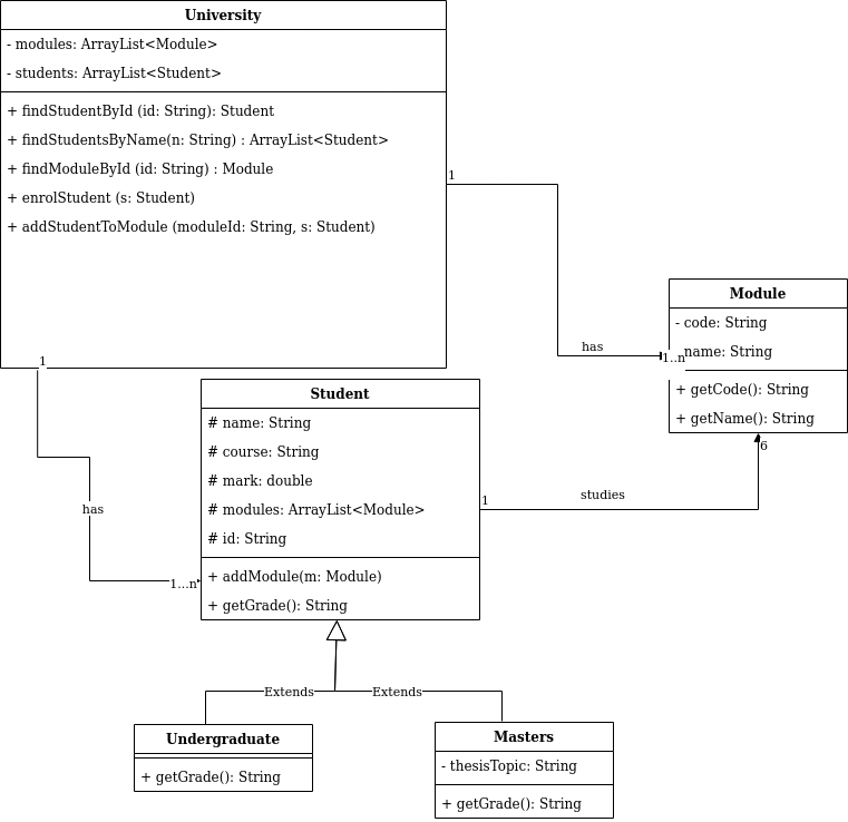
Each class is represented by a box, with content as follows:
Here is an example, based on the domain model above. Note that the addition of thesisTopic to the masters' student was not part of the domain model. I have added it here to help illustrate the inheritance hierarchy, but in a real case, you would not, at this stage, add things not in the domain model.
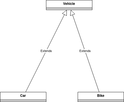
Inheritance in class diagrams
Inheritance in class diagrams is shown via an open arrow pointing at the superclass, for example:
Use cases
We may return to this in a later week, depending on how you are progressing.
The other step we need to take as an initial analysis and design step is use-case analysis. This takes a different approach to the problem compared to the domain model by considering the system from a user point of view; i.e. thinking about how the user will interact with the system. For example, we consider questions such as:
- Who are the users?
- How are they able to interact with the system?
After performing use-case analysis, we produce a
use-case diagram and then (ideally)
use-case texts.
An example use case diagram
A use case diagram shows:
- The actor(s)
- These are the external entities interacting with the system: typically, but not necessarily, humans (the university administrator in our example)
- Actors can be non-human, for example if an automated background process was interacting with the system (e.g. auto-removing students whose degree has finished) this would be an actor too
- Represented by matchstick figures
- The use cases themselves
- These are the tasks which the actors need to perform with
the system
- They can be derived by analysing the problem statement
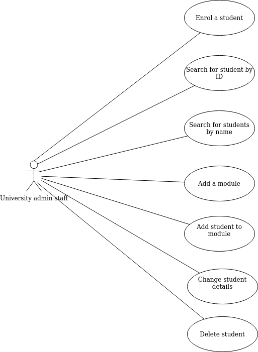
- e.g. for the university admin application, these could be:
- Enrol student
- Search for student by ID
- Search for students by name
- Create module
- Add module to student
- Edit student details
- Delete student
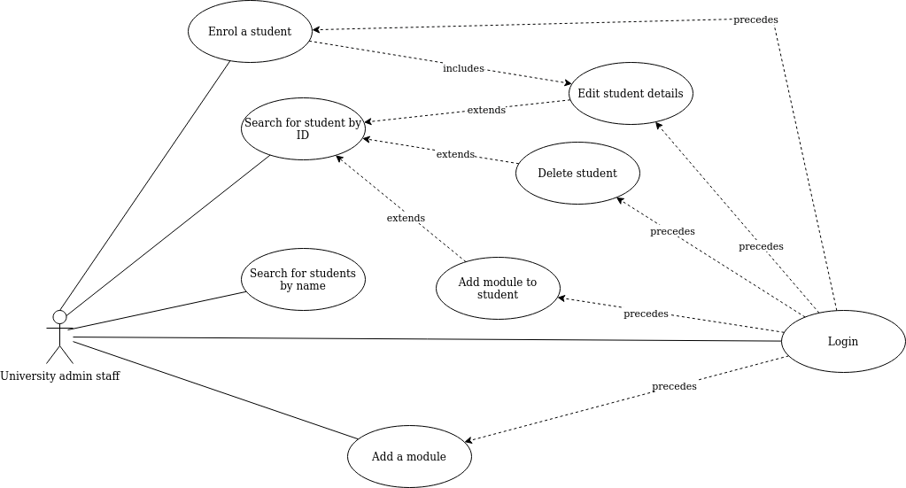
- From these, we would draw the use-case diagram below. Note the actor (matchstick figure) and use cases themselves (shown as ovals).
Dependencies between use cases
A more detailed use-case diagram will show dependencies between use cases. Dependencies include:
- A use case extending another; this is when the second use case is an optional extension of the first
- For example,
delete a student might extend search for a student, because after searching for a student object, the administrator might optionally delete it
- A use case including another; this is where the second use case is part of the process of the first
- For example,
enrol a student might include edit student details, because student details is part of the process of enrolling a student
- A use case preceding another; this indicates that the first use case must take place sometime before the second
- For example, the
login use case might precede enrolling a student, updating a student's details, or deleting a student
An example is here:
See
diagrams.net: "Draw a UML use case diagram".
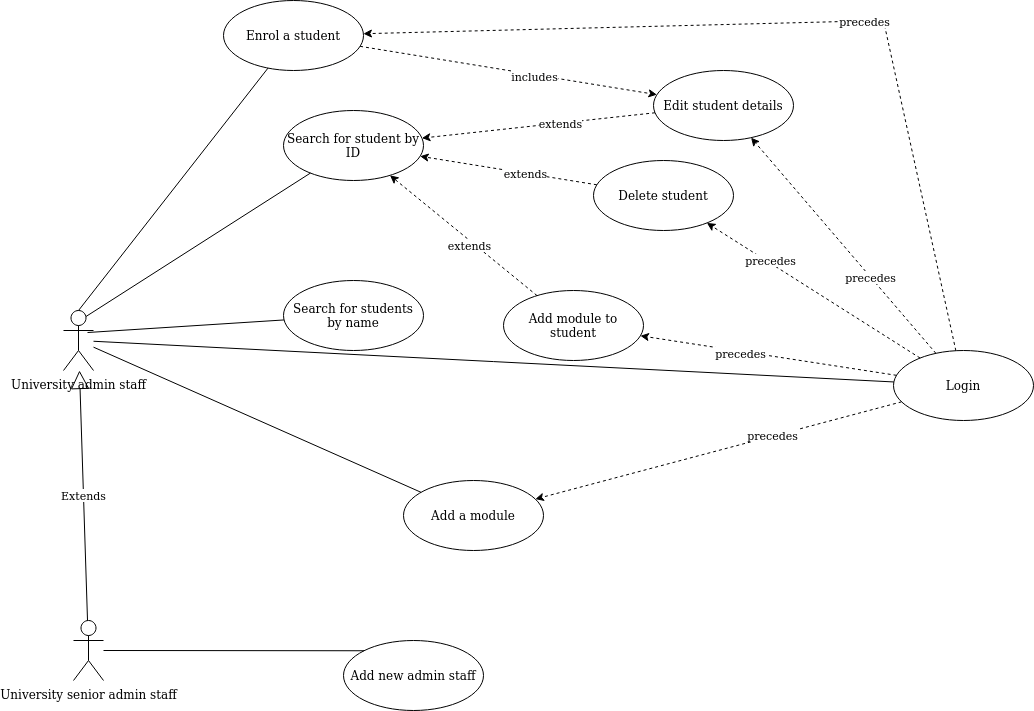
Generalised and specialised actors
- A use-case diagram can have more than one actor, as different use cases might be performed
by different actors
- Through use of the generalisation symbol in UML (an arrow with an unfilled arrow-head),
we can distinguish between generalised actors and more specialised actors
- An example for the university system might be if senior administrators (only) were allowed to add staff. The senior administrator is a more specialised version of the administrator, so they can do all use cases that administrators can do, as well as their own specific use case of adding a member of staff.
- The example below shows this
Use-case texts
The next step is to break down each use case shown on the diagram into a series of steps describing how a user will interact with the system in order to complete the use case. use-case text has two columns:
- Actor action, describing how the actor will interact with
the system
- System response, describing how the system will respond.
Example use-case text: Enrol student
| Step |
Actor action |
System response |
| 1 |
The use case begins when the admin staff selects to
enrol a new student. |
- |
| 2 |
- |
System prompts the user for the student details (name, address, date of
birth, course) |
| 3 |
The user enters the details specified in step 2. |
- |
| 4 |
- |
System checks validity of details, e.g. date of birth is sensible |
| 5 |
- |
System allocates student ID for new student |
| 6 |
- |
System enrols student in university |
| 7 |
- |
System confirms enrolment is successful |
Alternative courses of action
Our use-case text must also include alternative courses of action.
These describe how the system should react to errors, which
can help us design robust systems. These go below the main use-case text.
For example, in the previous use-case text:
At step 4: Date of birth is not sensible.
    Staff informed that date of birth is not sensible.
    Staff re-prompted for details (go back to step 3)
Example use-case text: Edit student details
This is a simplified version assuming includes or extends are not being used.
| Step |
Actor action |
System response |
| 1 |
The use case begins when the admin staff selects to
edit the student details |
- |
| 2 |
- |
System prompts the user for the student ID |
| 3 |
The member of staff enters the student ID. |
- |
| 4 |
- |
System checks that the student ID exists |
| 5 |
- |
System displays details of that student in editable text boxes |
| 6 |
The admin staff changes the details. |
- |
| 7 |
- |
System checks that the new details are valid (e.g. no blank strings) |
| 8 |
- |
System updates details of the student |
Alternative courses of action:
At step 4: Student ID does not exist on system
    Staff informed that the student ID does not exist
    Staff re-prompted for details (go back to step 2)

At step 7: New details are not valid (e.g. blank strings)
    Staff informed that the new details are invalid
    Staff re-prompted for details (go back to step 6)
Drawing the diagrams - diagrams.net
We will be using diagrams.net, an online piece of free software, to draw the diagrams. The labs will start with a live demo of this so please ensure you attend (or if you cannot attend, please ensure you watch the video later). diagrams.net have produced a very useful and extensive blog explaining how to draw different types of diagram. You will probably find the following particularly useful:
Exercise
Look at this problem statement:
There is a requirement for a piece of software to manage bands and bookings for
a live music venue. Customers should be able to view all events, search for and book events, as well as cancel bookings, on the web. Customers can also call the venue to book over the phone: venue staff should also be able to perform these tasks on behalf of customers when they book over the phone. Venue staff should be able to add and cancel events.
- Create a domain model for this problem statement.
- Add some likely attributes and methods to the domain model to produce a class diagram.
- Before moving onto use cases, ensure you have finished Questions 1-11 of Week 2, and the whole of Week 3. You need all these for the first assignment (the group project).